
V6/V8 Tach Ground Wire
#1
 05-18-2010

Thread Starter
|
Member

Joined: Apr 2010
Posts: 53
Likes: 0
From: Somewhere, TX
Guys I'm hoping y'all can help me as I humbly submit my 4cyl engine and v6/v8 instrument panel to you.
I cannot for the life of me find the wiring diagram I need for a 2001 or similar Sport Trac/Explorer instrument cluster.
This is the cluster I put in my 95 4cyl Ranger, the old cluster had no tach but the new one does. I just need to figure out clearly which wire I need to ground on the v8 cluster which now does not have the needed ground as my 4cyl did not come with or use one.
The thread below makes mention of it, but I'm unable to PM either user for clarity:
https://www.ranger-forums.com/f34/ga...llation-48800/
I beg you for your help! This tach is floating at 1500rpm and its so annoying!!!
#3
05-18-2010
Thread Starter
|
Member
Joined: Apr 2010
Posts: 53
Likes: 0
From: Somewhere, TX
#4
05-19-2010

Member
Joined: Apr 2010
Posts: 78
Likes: 0
From: Rapid City, SD
Hmm, not really sure.
In my 98, pin 16 was vacant, and moving the ground wire from pin 8 on c216 made it read correctly. I would assume that since you're using the same cluster, that pin (16 on c214) needs to be grounded to read the v8 correctly. If I'm correct, then yes, grounding it to the firewall would work fine.
I'm sorry, I'm home for a few weeks away from college, so i don't have my EVTMs here to check out any other differences.
Chris
#7
05-19-2010
Member
Joined: Apr 2010
Posts: 78
Likes: 0
From: Rapid City, SD
#8
05-19-2010
Thread Starter
|
Member
Joined: Apr 2010
Posts: 53
Likes: 0
From: Somewhere, TX

#11
05-19-2010

There are a couple of problems with using a late cluster in a 95.
First of all, there are several wiring mismatches.
Second, the connectors pin number assignments used in the diagrams for each of the three connectors are reversed. Using the sixteen pin connector for example, 1=16, 16=1, 3=14, 9=8, etc.
Late clusters differentiate 4, 6 and 8 cylinder by which ground wires are connected.
Pin 16 of the 16-pin grounded ==> V8
Pin 8 of the 10-pin grounded ==> V6
I think that both disconnected means it's a 4-cylinder.
In the 95 diagrams, as mentioned above, the pin number assignments are reversed in the cluster connectors. So, the above translates to:
Pin 1 of the 16-pin grounded ==> V8
Pin 3 of the 10-pin grounded ==> V6
I think that both disconnected means it's a 4-cylinder.
The #3 pin assignment in the 95 ten-pin is currently for the PCM ground trigger for the MIL (CEL). So, it's a pretty safe bet that it isn't going to be functional with the replacement cluster. I didn't go through every pin but I would be surprised it there are not several other incompatibilities.
#12
05-19-2010
Thread Starter
|
Member
Joined: Apr 2010
Posts: 53
Likes: 0
From: Somewhere, TX
There are a couple of problems with using a late cluster in a 95.
First of all, there are several wiring mismatches.
Second, the connectors pin number assignments used in the diagrams for each of the three connectors are reversed. Using the sixteen pin connector for example, 1=16, 16=1, 3=14, 9=8, etc.
Late clusters differentiate 4, 6 and 8 cylinder by which ground wires are connected.
Pin 16 of the 16-pin grounded ==> V8
Pin 8 of the 10-pin grounded ==> V6
I think that both disconnected means it's a 4-cylinder.
In the 95 diagrams, as mentioned above, the pin number assignments are reversed in the cluster connectors. So, the above translates to:
Pin 1 of the 16-pin grounded ==> V8
Pin 3 of the 10-pin grounded ==> V6
I think that both disconnected means it's a 4-cylinder.
The #3 pin assignment in the 95 ten-pin is currently for the PCM ground trigger for the MIL (CEL). So, it's a pretty safe bet that it isn't going to be functional with the replacement cluster. I didn't go through every pin but I would be surprised it there are not several other incompatibilities.
First of all, there are several wiring mismatches.
Second, the connectors pin number assignments used in the diagrams for each of the three connectors are reversed. Using the sixteen pin connector for example, 1=16, 16=1, 3=14, 9=8, etc.
Late clusters differentiate 4, 6 and 8 cylinder by which ground wires are connected.
Pin 16 of the 16-pin grounded ==> V8
Pin 8 of the 10-pin grounded ==> V6
I think that both disconnected means it's a 4-cylinder.
In the 95 diagrams, as mentioned above, the pin number assignments are reversed in the cluster connectors. So, the above translates to:
Pin 1 of the 16-pin grounded ==> V8
Pin 3 of the 10-pin grounded ==> V6
I think that both disconnected means it's a 4-cylinder.
The #3 pin assignment in the 95 ten-pin is currently for the PCM ground trigger for the MIL (CEL). So, it's a pretty safe bet that it isn't going to be functional with the replacement cluster. I didn't go through every pin but I would be surprised it there are not several other incompatibilities.

With your post here and the pm from RPS I guess I'm supposed to try removing grounds until one makes it work right? Everything on the dash works surprisingly well except for the Tach, but whats the verdict about the 95 grounds being in totally different places?
I know for a fact that the Sport Trac cluster was from a v6 as that was the only engine available for that model/year.
That being the case, a ground at pin3 on the 10pin connector only, and no other grounds in the designated spots (ie pin1 of the 16pin connector) should make it work, correct? I emphasize SHOULD lol.
I also should note, the door ajar doesnt work, and frankly I didnt know it existed, not that I care. So ground pin3 of the 10ping connector on my 95 4cyl harness shouldnt be an issue I guess.
#13
05-19-2010
Member
Joined: Apr 2010
Posts: 78
Likes: 0
From: Rapid City, SD
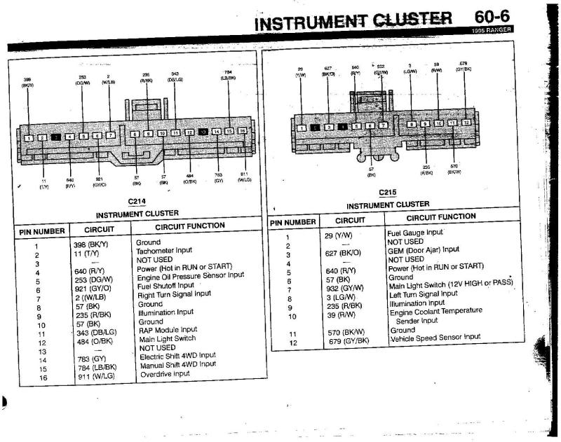
Here's the much anticipated 98 pin-outs. Your best bet is to try to match your wiring to them I'd think. Should be pretty easy since it looks like you have access to the 95 EVTM. Good news, it also mentions which one to leave ungrounded for 4cyl.
(sorry about the quality, no scanner here so i just took pics :P)


(sorry about the quality, no scanner here so i just took pics :P)
#14
05-20-2010
Thread Starter
|
Member
Joined: Apr 2010
Posts: 53
Likes: 0
From: Somewhere, TX
Awesome! Thanks a77cj7, looks like exactly what I need. 1 Problem, I dont actually have the 2nd pic that contains the c216 for a 95, only the one pic I posted. You wouldnt happen to have that would you?
And your pinout brings up another question: Do I make sure pin8 on c216 is grounded for the sake of the v6 cluster, or do I remove the ground for the sake of the 4cyl truck? I guess it would be which ever it is currently not, in order to make it function properly?
And your pinout brings up another question: Do I make sure pin8 on c216 is grounded for the sake of the v6 cluster, or do I remove the ground for the sake of the 4cyl truck? I guess it would be which ever it is currently not, in order to make it function properly?
Last edited by arownious; 05-20-2010 at 12:15 AM.
#15
05-20-2010
Member
Joined: Apr 2010
Posts: 78
Likes: 0
From: Rapid City, SD
Sorry, i don't have the 1995 evtm, i only have the 1998 ranger one and the 1997 exploder one.
Looks like ya need to find someone on here with a 95 EVTM, i'm sure someone has one.
I would try it not grounded first, as the manual indicates.
If 96 and 95 are the same (don't remember), you could try PMing "Topdog2007". He's got an awesome writeup on v8 swapping his 96, and he's likely to have the EVTM for that reason.
Or PM "ford rules". Hes got a v8 swapped 95, so again, likely has the EVTM.
Or just buy the damn EVTM off ebay for 10 bucks, but ya have to wait on shipping that way.
#18
05-20-2010
Member
Joined: Apr 2010
Posts: 78
Likes: 0
From: Rapid City, SD
I have no idea about wire color. You really need to get a copy of connector 216 from the EVTM.
As to being backwards, i simply mean that in yer 95 pinout, the plugs are numbered left to right, and in the 98 pics, the plugs are numbered right to left.
The good news is that it looks like most of the wires are the same.
For the first two plugs:
all referenced from 95 evtm
C214
Pin 1: cut wire, not used
Pin 6: switch with wire from Pin 3 on c215 (both wires should be switched and reconnected)
Pin 8: cut wire, not used
Pin 13: needs cruise control imput for light, no big deal
C215:
Pin 3: already switched with Pin 6 on c214
Pin 4: malfunction lamp input. According to bob's post, repin with wire 3 from c216
So really you just have to cut a few excess grounds and switch two wires. The cruise light input is no big deal, and you don't have to worry about it. Likely, its on plug 216 though.
Last edited by a77cj7; 05-20-2010 at 01:15 AM.
#19
05-20-2010
Member
Joined: Apr 2010
Posts: 78
Likes: 0
From: Rapid City, SD
Just realized something, since pin 1 in connector 214 is currently grounded, the tach is set for a v8. Cutting that wire may make the tach work correctly. I would do the rest of the mods while you're there though, and find the diagram for 216 to mod that too.
Also, since bob says that wire 3 in 216 is the CEL ground, when your truck trips a CEL, the tach would go to v6 mode
Looks like Bob has access to the 95 EVTM, so hopefully he'll post up plug c216 for you.
EDIT: make sure you read my other reply on the previous page, it tells you how to mod the plugs by using your 95 printout.
Last edited by a77cj7; 05-20-2010 at 01:25 AM.


#22
05-20-2010
Thread Starter
|
Member
Joined: Apr 2010
Posts: 53
Likes: 0
From: Somewhere, TX
C214
Pin 1: cut wire, not used
Pin 6: switch with wire from Pin 3 on c215 (both wires should be switched and reconnected)
Pin 8: cut wire, not used
Pin 13: needs cruise control imput for light, no big deal
C215:
Pin 3: already switched with Pin 6 on c214
Pin 4: malfunction lamp input. According to bob's post, repin with wire 3 from c216
#24
05-20-2010
Member
Joined: Apr 2010
Posts: 78
Likes: 0
From: Rapid City, SD
Finalized list:
all referenced from 95 evtm
C214
Pin 1: remove wire, not used
Pin 6: switch with wire from Pin 3 on c215 (both wires should be switched and reconnected)
Pin 8: remove wire, not used
Pin 13: needs cruise control imput for light, no big deal
C215:
Pin 3: already switched with Pin 6 on c214
Pin 4: malfunction lamp input, repin with wire 3 from c216
C216
Pin 2: remove wire, not used (tape as it is a hot wire)
Pin 3: Wire already switched to pin 6 on c215, leave blank for 4cyl or add one of the extra grounds from c214 for a v6
That should cover it.
As bob said, these wires are relatively easy to repin with a very small screwdriver. I moved one of mine that way.
O, and CEL = Check Engine Light. Its good to keep it working correctly.
Chris
#25
05-20-2010
Thread Starter
|
Member
Joined: Apr 2010
Posts: 53
Likes: 0
From: Somewhere, TX
Alright here is an update. I snipped pin3 on c216 because I could not get the pin out. I checked pin1 on c214 and it was not grounded so I left it alone as well as pin8 even though this was grounded. Since its unused in the new cluster I decided it was better left alone.
Simply snipping pin3 from c216 made the tach work. It still seems a little sluggish in 4th and 5th gear, but I'll need to take it out on the highway tomorrow to make sure. I'll have to fix the other issues in a few days like the check engine light.
Simply snipping pin3 from c216 made the tach work. It still seems a little sluggish in 4th and 5th gear, but I'll need to take it out on the highway tomorrow to make sure. I'll have to fix the other issues in a few days like the check engine light.


