When you click on links to various merchants on this site and make a purchase, this can result in this site earning a commission. Affiliate programs and affiliations include, but are not limited to, the eBay Partner Network.
I made the mistake of pulling the passenger valve cover yesterday to see how things were goin' in there. Rear cassette top bolt slot was cracked, so I pulled the engine. I've been anticipating this since I bought the truck with 170k on it last year.
I'm deep into the rebuild as of tonight. Got the heads off yesterday and dropped them at the shop for lapping and decking. They look great considering the mileage they've seen, and it looks like I'm the first one this deep in the engine since the factory.
"So", I said to myself, "I've got it out and smiling on the stand, may as well throw a grand worth of new parts at it".
And as I began to tear into it, what do I see but a fractured tensioner on the jackshaft timing chain. What a catch. I wouldn't want to be driving when that sucker let loose.
Tomorrow I have a date with a bottle of acetone and a brass brush, gonna shine that block up the best I can. I will update with some photos as I get everything clean and ready to go back in. I am sure to run into numerous complications as the job progresses, not the least of which is my lack of a jackshaft sprocket holding tool. I improvised with the front sprocket bolt torqued down and a rag on the sprocket to break the rear bolt free, but setting torque when I'm timing it is still unclear to me. Anyone else get this done with just the timing tool kit? I might need to make a tool for it, no way I'm spending $100 on a wrench I'll hopefully never use again.
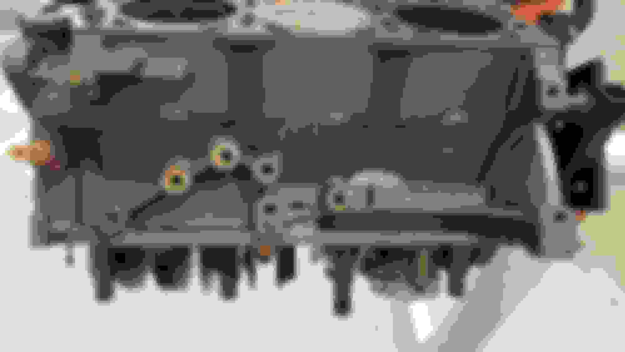
It's taking longer than I had figured to get the gasket surfaces cleaned. I've got some photos of where I've gotten it to as of today,
and what I started with.
Will the head gaskets be able to handle all the pitting and tarnish I can't get off with a brass brush and razor blades?
I'm surprised there weren't any gasket failures considering how corroded some areas of the block are.
I"m not going to deck the block, it's not worth it to me at this point, just curious if anyone thinks this shiz won't fly. Also, it looks like something made it into the rings, cylinder 6 has a gash.
Tonight and tomorrow I'll be chasing threads and cleaning bolt holes, cleaning off all the bolt-ons, and repairing any wiring harnesses as I clean the bay a bit. Definitely replacing all the hoses, and new motor mounts going in too.
If anyone has tips I would appreciate advice. I know to prime the oil pump, lash adjusters and tensioner before installing, and also the clear flooded engine routine before startup to further prime the oil system. Should I drain the coolant and replace shortly after rebuilding like I will be with the oil? Any other common sense stuff they don't feel the need to include in the service manual?
So it's been almost a week, and in still waiting on a few bits and pieces to make it here from ford. I've been tinkering with this and that, trying to clean up the wiring and accessories as best I can with limited supplies. I read a thread on a hot rod forum regarding the use of SLIP plate graphite coating on exhaust manifolds. I decided to give it a shot, and it looks really slick, pun intended. Then I decided to get crazy and slap some on the block and see how it holds up. I took a wire brush to the manifold after the first coat and while I was able to get some of the graphite off, it is a remarkably sturdy finish for something that's supposed to be a dry lube. Only time will tell but so far it seems like an easy solution for finishing metal parts.
Here's how it looks after applied and cured.
And here's the finish after being buffed by hand with a rag. I'm sure you could get it crazy shiny with a buffer wheel and more patience than I have.
Here's how the manifold turned out.
Before pics for reference.
Last, the valve covers and intake after cleaning and trim restore.
Looking good! Did you buy all those special tools to keep the cams locked in place?
Are you going back with the Cloytes parts?
I did get the OTC tool kit, and I would recommend it. Two reasons. One, the tensioner they include sets the drive side of the chain guide to the proper tension to keep cam sprockets in phase with jackshaft when tightening the cam sprocket bolts. You could try to make a tool with an old tensioner but how much is your time worth? Two, since none of the jackshaft or camshaft sprockets have key ways, holding them still during bolt tightening is incredibly difficult. Without the tools, you would have to lock both sprockets and tighten the sprocket bolts without the chain moving at all.
As for parts, I went with ford. Because it cost so much to get stuff shipped to Hawaii, it ends up being the same price for parts from the dealership as it is on fpg or rock auto. I would be fine with using the cloyes set, but I would still go with motorcraft tensioners and fel-pro or ford head gaskets and bolts.
So I fluffed up but I realized my mistake and only set myself back a day.
I got the heads back from the shop today, and they looked real nice. I sprayed out the gallery and every passage and port and nothing came out. Guess they cleaned them. Stupid me forgot to check the oil flow restrictor in the driver side head before I torqued it on the block. The machine shop also didnt think to check this port. It was packed full of sand and gunk. Whoops. So I pulled it off, and the shop was nice enough to take them back and re-clean them for me. Tomorrow after lunch I'll have a new gasket set and new head bolts and shiny clean heads to bolt on. At least I didn't feed my cam journals a tablespoon of sand on my first start.
Yeah, I got lucky and found a set of those used OTC tools for like $175. I always wondered what kind of cheap plastic guides that Cologne Germany plant used from 2001 - early 2004 to make them break so easily. (Maybe the parts were made in China.)
I guess you already know this, but that back cam bolt has left handed threads. There's been a lot of people break that thing off because they turned it the wrong way.
Is yours a 4X4 with the jackshaft in it?
Since you already have the heads off are you going to install the timing chains and sprockets before you put the heads back on?
Is yours a 4X4 with the jackshaft in it?
Since you already have the heads off are you going to install the timing chains and sprockets before you put the heads back on?
BTW � that's a good looking heart.
Yes it's a 4x4, but this engine doesn't have a balance shaft in it. Either someone already swapped the old engine out for this one from a 2wd, or this one came from the factory without a balance shaft. I have heard that some 4x4 rangers came without the balance shaft, but I'm leaning toward this being a swapped engine. One of the engine mounts was newer than the other, and I saw a few other signs of previous work(snapped exhaust studs in the down pipe flange).
As for the timing chain sprockets and guides, I'm doing a bit of both. I get the front jackshaft sprocket, guide and chain installed before the head. I also install the rear jackshaft sprocket and chain before the head. I get all the crank timing guides on, tension the main chain, then use a breaker bar on the crankshaft (29mm fits over the shaft and locks on woodruff key) to hold the jackshaft sprockets while I torque their bolts down. This way I dont need that $200 wrench to hold the rear sprocket. Once they are tight, I'll bolt the heads down and then feed the rear guide in through the head. The front guide is tough to feed down through the head but the rear one just drops in. At this point I'll install the camshafts and proceed with timing. The only sprockets that need to stay freewheeling during timing are the cam sprockets, so its okay to torque the jackshaft sprockets before the heads are on. I'll be setting the timing up this evening, so I'll take some photos to clarify that process a bit. The service manual tells you to install both guides and then install the heads, so that will work just as well. I just always end up getting oil on the head gasket surfaces when the guides are in the way. It also makes torquing the two tiny head bolts harder as the guide is in the way.
So I went ahead and tried to torque down the jackshaft bolts. What a nightmare. So the front bolt is 33 ft lbs then 90� and the rear bolt is 15 ft lbs and 90�. I made sure to draw my 90� marks as soon as I hit the 15 ft lbs on the back. Then I used the back bolt to hold the jackshaft while I got the front to 33 ft lbs. In the process I torqued the rear bolt about 15�. Now I marked the front bolt 90� and began to turn the two against each other. I was using a 3 ft breaker bar on both so I didn't need to strain so much, but for some reason the front made it to 90� way before the back did. To make matters worse, the rear sprocket turned with the bolt. I made marks from the sprocket to the bolt and from the sprocket to the block, but I'm still not 100% sure I made it to 90� on the rear bolt. If the sprocket slipped and the bolt didn't turn with it, then I'm only at around 50�. I feel like the odds of this are pretty low considering how much force I applied to that bolt. Its gotta be in the 150ft lbs area, I was really cranking on it. So to put my mind at ease, I ran a chain from the properly torqued front jackshaft sprocket to the block to lock it in place, then I gave the rear bolt one more crank and couldn't budge it. If it isn't torqued down I'm afraid I'll strip that t55 torx head before I make it any further. Here's how the rear looked after tightening it down, you can see how the sprocket spinning makes it look like I'm only at 45�.
I'm preparing the heads for install. I noticed that the thermostat flange had some deep pitting directly along the seal line. I skimmed some red rtv into the pitting to show how deep it is. Should I have this machined down? The gasket that seals the thermostat looks like a wide rubber-band and doesn't offer much sealing surface to begin with.
The two small red dots are where the gasket sits.
I didn't get ahold of the head gaskets until 2PM, so I didn't make it onto the crane yet. The timing is set, spun the engine a few times and it's all good to go.
I had to reposition the drivers side cam caps three times until I got close to their original seat. It spins alright, but it is a tad tighter than the passenger side. Its difficult to get the caps on straight, since there is so much slop in the bolt holes. If one were not careful one could install a cap at nearly a 5� slant. Imagine your cam caps oriented as such:
===/====\====/===|=
You'll notice right away if they're crooked, cam won't spin well at all. You should be able to spin the cam by hand without too much effort, definitely shouldn't need leverage.
Anyway, I'm pretty much done with the technical stuff, the damn timing procedure took all of 30 minutes. I spent more time cleaning bolts.
That's as far as I made it today. I plan to have it ready to install by mid day tomorrow.
SWEET! It looks like things are coming along rather nicely. (Those heads are super clean!) It looks like you got that back jackshaft bolt tightened down REAL good. Did you use any lock tight on it?
SWEET! It looks like things are coming along rather nicely. (Those heads are super clean!) It looks like you got that back jackshaft bolt tightened down REAL good. Did you use any lock tight on it?
I didn't. I would have liked to, but everywhere I read said not to use locktite on torque to yield bolts. I just used a bit of oil to lube the threads and head so it didn't grab as I was tightening it. I hate the idea of relying on torque and friction to keep the timing on this engine, why the hell don't they have key ways on any of these sprockets?
Got a lot done today. I bolted together the block and cradle and finished up the valve train. The block to cradle took a while, I had to pull it apart, clean, and try again to get the back flat. What's the secret? Beats me. I was prepared for it to be off again but it was as perfect as I cared to get it, couldn't even scoot a .0015 feeler underneath it. I flushed the back with a straightedge, then tightened one back edge bolt. Then I checked straight again and tightened one more. Rinse and repeat with the first 8 bolts or so just to be safe. And hurry, because theres sealant going off as you do it. The timing cover was much easier.
New lash adjusters and roller rockers, new springs. Reused everything else.
I got everything I could back on before attempting to put it back in the truck.
I got all the trans bolts threaded in and the engine mounts in place, but I couldn't line the mount to block bolts up and had to call it a night. Tomorrow all the rtv gasket will be set and I can fill 'er up. Exciting.
Got it in and back together. Start it up, and she runs. So far so good. Mechanically, the engine sounds great. It's running like crap though. At idle, it surges from 750 rpm down to 200 or so and back up in 1 second pulses. If I give it throttle it revs up and runs fine, no misfires. No vacuum leak, fuel system is fine. I'm thinking that it's possible I created an electrical issue while moving things around. I did get two codes out of it, a p0320-c and a p0320-p. They both relate to the crank sensor.
Is it possible that by replacing the harmonic balancer and therefore changing the tone ring that my crank sensor is having trouble with the new setup? Seems unlikely to me.
I'd love ideas or tips if anyone has them, my next step is wiring diagnostics, which is just slightly less painful that pulling teeth.
Well I went at the electrical grounds this morning, made sure they're all solid. Checked the wiring from ckp to pcm and its intact. Pulled and cleaned the o2 sensor plug that's after the ckp. Also pulled the pcm and took a look at the board. It's the cleanest pcb I've ever seen. So I hooked up my scanner, did a quick koeo self test, all systems go. Fire it up, and aside from a stumble right as it cranked over she ran fine. Normal idle, 0 fuel trim, and no more p0320. So either I had a loose ground on the pcm harness or I've got a ghost in the wires playing with me. I'm gonna take her out for the inaugural test drive later today, and will know more based on that. I know that I should pull the harness and hand trace every wire but I just really don't wanna do that.
Well I went at the electrical grounds this morning, made sure they're all solid. Checked the wiring from ckp to pcm and its intact. Pulled and cleaned the o2 sensor plug that's after the ckp. Also pulled the pcm and took a look at the board. It's the cleanest pcb I've ever seen. So I hooked up my scanner, did a quick koeo self test, all systems go. Fire it up, and aside from a stumble right as it cranked over she ran fine. Normal idle, 0 fuel trim, and no more p0320. So either I had a loose ground on the pcm harness or I've got a ghost in the wires playing with me. I'm gonna take her out for the inaugural test drive later today, and will know more based on that. I know that I should pull the harness and hand trace every wire but I just really don't wanna do that.
P0320 Ignition/Distributor Engine Speed Input Circuit Malfunction
Is not technically a Crank sensor code
These are crank sensor codes:
P0335 Crankshaft Position Sensor A Circuit Malfunction
P0336 Crankshaft Position Sensor A Circuit Range/Performance
P0337 Crankshaft Position Sensor A Circuit Low Input
P0338 Crankshaft Position Sensor A Circuit High Input
P0339 Crankshaft Position Sensor A Circuit Intermittent
But P0320 is generated because crank timing is OK, BUT...............there is a erratic signal coming from it that doesn't fit any of the above codes
Engine simply won't start unless it has a valid timing signal, and yours did start
Not so fast, I think I found some bad news. So truck started hunting at idle again, p0320 code again, back to square 1. I found this test procedure for the ckp specifically.
results:
0 ohms from ckp + and - to PCM harness pins.
Tells me no wire issues from sensor plug to pcm?
0.0 volts from battery neg terminal to cpk harness + with key on
Tells me voltage isn't making it past pcm?
I still need to check voltage and ohms from PCM harness to battery, so I'm gonna figure out how to do that, but the results I got indicate replace PCM. I really don't like that. I read something about the 2004 dash and PCM being linked and replacing one without the other isn't possible?
There's something else. I've had a p0704 for months. I replaced the switch and still had the code. It didn't affect drivability that I could notice, so I haven't tried to source it. I assumed it was a frayed wire in the dash. Now the other possible outcome for a p0704 that isn't the switch or its wiring harness is a bad PCM, says replace just like the p0320 test procedure.
Thanks, I'll try that as well. I must have misunderstood the purpose of the tests I was performing. I thought that the bias voltage test was to check for continuity between the ckp, the PCM, and the rest of the wiring harness. Not whether or not the ckp was functioning. As you said, engine won't crank without a signal from ckp saying "timing looks good", so sensor doesn't seem to be the issue.
But you tested wires and they were 0 ohms, did you test them between ground and wire as well so neither was shorted to ground?
I think that was part of the test above, but not sure why you would expect a voltage with key off
With key on I can see a slight voltage, 1-2volt, as that would be a test if CKP was hooked up and not an open circuit, a monitor voltage
Yeah, so that's what I was trying to test. Test parameters were:
Key on, engine off.
PCM harness connected
Ckp harness disconnected (for testing)
Testing for voltage between ckp+ and bat- shows 0.0v
Testing for voltage between ckp- and bat- shows 0.0v
also tested:
Key off
PCM harness disconnected (for testing)
ckp harness disconnected (for testing)
Testing for resistance on ckp+ at ckp harness and PCM
Testing for resistance on ckp- at ckp harness and PCM
Both wires show no resistance
Unless I am missing something, doesn't this mean that the PCM has failed the bias voltage test for ckp? I was supposed to see between 1 and 2 volts correct? Thanks for helping with this Ron, I just want to be sure I am not gonna have ford put a new PCM in and kill it with a wiring problem I missed.

 04-22-2020