When you click on links to various merchants on this site and make a purchase, this can result in this site earning a commission. Affiliate programs and affiliations include, but are not limited to, the eBay Partner Network.
The idea behind this mod is to be able to control the A/C Compressor with a single switch. This duplicates the blue "A/C" switch that is found in many automobiles. You can then leave the A/C control in the MAX position, and recirculate chilled air without running the compressor. Basically, this mod will cut circuit 348 (A/C demand signal) which tells the PCM (Powertrain Control Module) that the A/C control panel is in a selection that uses the A/C compressor. This mod does not interfere with the PCM, it just interrupts the signal send from the A/C panel.
This procedure was researched using the Ford service CD and has been verified by technicians who work at Ford dealerships.
I want to credit my bro Mark (Red Dog) who helped me design this mod, which is why I call it the G&M A/C Mod.
Tools/Equipment needed:
Screwdriver Set
Dremel Tool/Drill
On/Off Toggle Switch
Spade wire connectors
INSTRUCTIONS...
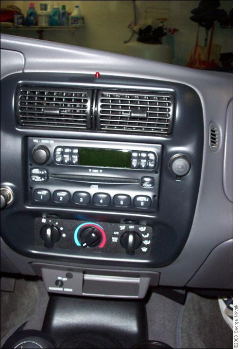
To start, you must remove the center panel in the dash. You begin by removing the two screws above the A/C control panel. Then, get your fingernails behind the panel and pull forward. It will slide out towards the rear of the truck.
To remove the panel, you disconnect: The radio (red connector), Antenna (silver banana plug), Cig Lighter (two connectors on left), Aux 12 volt power plug (connector on right). If you have fog lights, there is an additional connector on the right side.
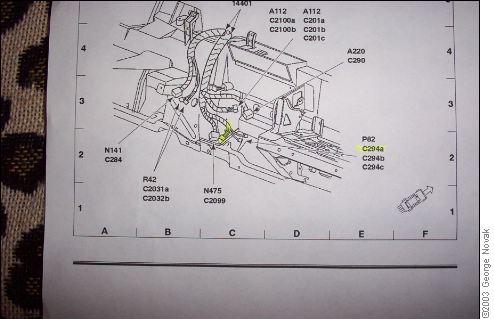
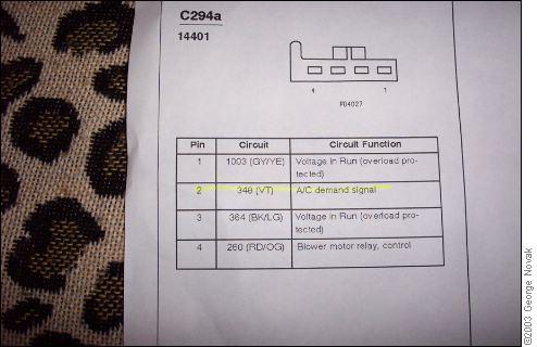
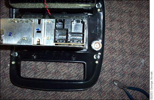
Here's the Ford diagram of all the wires with the entire dash apart. The connector you are after is 294A. It has 4 wires in it, it's red, and it connects behind the A/C panel. It's a little right of the center.
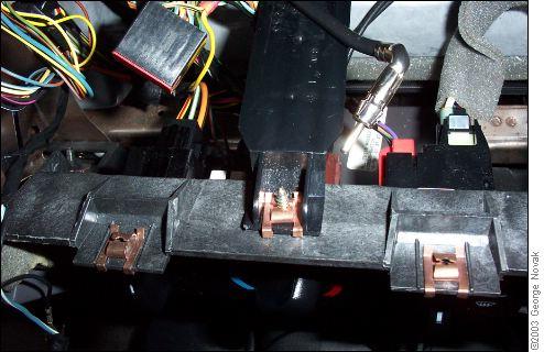
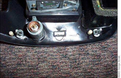
This is Connector 294A under the antenna plug. Use a screwdriver to release the catch. The violet (purple) colored wire on top is the one we will cut for adding the switch. I added two short wires with spade connectors to make it easier.
This is the Ford chart for connector 294A. The A/C demand circuit is where we add the switch. This will interrupt circuit 348, which tells the PCM to turn on the compressor. Cut the Violet wire and add your switch.
I installed my switch above the Cig Lighter using an existing mounting spot. To get the area flush, I first cut off the raised plastic mounting box area.
I next used my dremel to cut and smooth the area, so my switch will fit flush. Then drill the proper size hole and install the switch. I used a metal one from Home Depot after my plastic Radio Shack one broke it's nut.
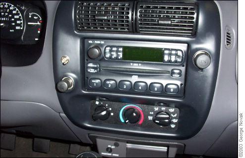
Now put the panel back, making sure the radio slides into it's rail. Reconnect the radio and other connectors. Connect the new switch (I used spade connectors). Replace the screws over the A/C control panel.
Mod Complete:
Edited by Jason Gonderman (rngprerunner) for grammar and format.
Last edited by 98liftedranger; 11-27-2011 at 11:44 PM.
I'm looking at wiring diagrams and then I'm like..... "****.... someone has HAD to have done this already.", I mean, I can't be the only one getting annoyed.
Just did a search for "ford ranger disable ac with switch" and bam! Done! Thanks for posting this.
My ranger has the fuse panel on the passenger side floor. The wiring also looks different from the above guide. The guide above will work in place of the colored wires shown below (wires are in the same place just colored differently). On mine I interrupted the green orange wire instead of the + feed into the selector switch.
 06-24-2005